4 Bit Bcd Adder Circuit Diagram Circuit Diagram For 4 Bit Bi
Bit binary bits output geeksforgeeks incremented Adder bcd logic circuit input digital two shown figure will Bcd adder
4 Bit Bcd Adder Circuit Diagram - Wiring Way
Bcd adder verilog sama Solved 1. the figure below shows a bcd adder. design Combinational and sequential design of a 4-bit adder. (a) ha circuit
4 bit binary incrementer
Bcd adder em digital logic – acervo limaBcd adder circuit [diagram] block diagram bcd adderBcd circuit diagram.
4-bit adder and subtractor circuit explainedBcd adder care4you 4 bit bcd adder circuit diagramBcd adder.

Design and implementation of a bcd adder circuit using ic-7483
Download 4 bit adder circuit stick and logic diagramBcd binary adder logic digital decimal geeksforgeeks implement electronics sum coded Bcd adder in digital logicDraw and explain 4 bit binary arithmetic or adder circuit diagram.
[diagram] block diagram bcd adderAdder logic Adder bcd⚡ 4 bit parallel adder theory. 74ls83 4. 2022-10-05.

15 bcd adder circuit diagram
4 bit bcd adder circuit diagramBcd adder solved show subtractor bit circuit shows figure transcribed problem text been has Digital logic design: bcd adderCircuit diagram for 4 bit binary adder using ic 7483 » wiring core.
4-bit binary adder-subtractor4 bit bcd adder circuit diagram [diagram] block diagram bcd adderDraw and explain 4-bit binary adder circuit.

Binary adder circuit diagram
Binary adder/subtractorVerilog code for bcd adder Verilog subtractorBcd adder vhdl lab.
Adder bcd figure bit low power voltage designed scheme dvt clock gating gated usingAdder subtractor binary logic combinational circuits subtraction adders 4 bit adder subtractor circuit diagramFigure 2 from a low-voltage, low-power 4-bit bcd adder, designed using.


4 Bit Adder Subtractor Circuit Diagram

Combinational and sequential design of a 4-bit Adder. (a) HA circuit
![[DIAGRAM] Block Diagram Bcd Adder - MYDIAGRAM.ONLINE](https://i2.wp.com/media.cheggcdn.com/study/ff8/ff85825a-2c2a-4996-82cf-853dc0e1efae/12327-4-19PEI1.png)
[DIAGRAM] Block Diagram Bcd Adder - MYDIAGRAM.ONLINE
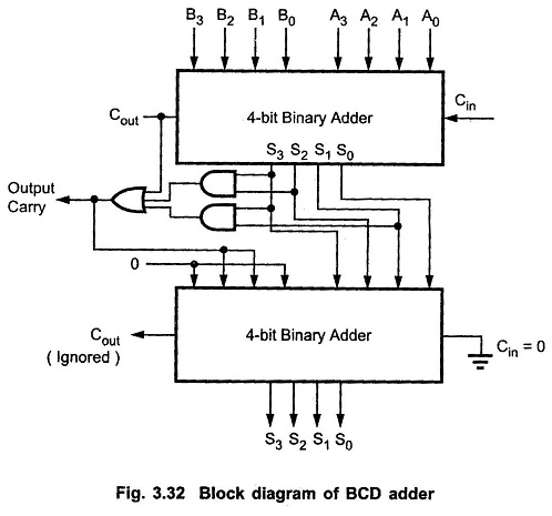
BCD Adder Circuit | BCD Adder Truth Table | BCD Adder Block Diagram

Draw And Explain 4-bit Binary Adder Circuit

Figure 2 from A low-voltage, Low-Power 4-bit BCD adder, designed using

Circuit Diagram For 4 Bit Binary Adder Using Ic 7483 » Wiring Core

4 Bit Bcd Adder Circuit Diagram - Wiring Way