4 Pipe Hvac System Diagram Hvac Air Conditioning Ahu Layout
Hvac system 4 rows 4 pipe modular air handling unit Hvac utilize multifamily purge smoke february piping hydronic Central air conditioning unit installation
HVAC System - How Does it Work, Components and Maintenance Tips
Hvac system How hvac systems work diagram The schematic diagram of the investigated hvac system.
How to read wiring diagrams in hvac systems
How does your hvac ductwork work?Schematic diagram of ducted air conditioning system [diagram] rtu hvac diagram[diagram] simple hvac ladder diagrams.
2 pipe versus a 4 pipe system — university housing and the residentHvac principle conditioning wiring [get 20+] schematic diagram structure meaningHvac conditioning furnace heating ducts handler cooling conditioner ductwork ventilation refrigeration.

Circuit wiring diagram examples hvac training sik experiment guide for
Hvac conditioner ductwork conditioning duct ducted simple infographic ducts ventilation plumbing refrigeration mini pipes connects functions packagedCooling tower piping schematic diagram Mep site: four pipe hvac systemPipe hvac system four two chillers boiler mep site types.
Oil pumping unit diagram speed motor starter dol control power beam field gas electrical double instrumentation engineeringHow 2 & 4 pipe hvac systems utilize energy? A good a/c system diagramHvac air conditioning ahu layout system detail installation panel work not saved google kitchen power.

Oil and gas electrical and instrumentation engineering: oil field beam
[diagram] wiring diagrams for hvac unitsThis simple diagram shows you how your hvac system's ductwork connects Hvac principle components wiring databaseDiagram of hvac system.
How 2 & 4 pipe hvac systems utilize energy?4 way valve working system hvac work, heat pump air conditioner, ladder Ahu hvac air rows pipe system handling unit modularPipe hvac chilled housing includes.

Hvac system schematic
Inside industrial large hvac heating ventilation and air conditioningDiagram system ac air conditioning unit hvac components cooling heating central conditioner anatomy cleaning furnace outside diagrams duct callie broaddus Hvac systemAc schematic wiring schematic.
2 pipe versus a 4 pipe system — university housing and the residentImage result for ahu layout Chilled housing coil hvac louisvilleHvac conditioner ductwork conditioning ducted duct infographic ducts ventilation residential plumbing refrigeration pipes wiring.

1 schematic diagram of a typical hvac system
.
.


How 2 & 4 Pipe HVAC Systems Utilize Energy? - InnoDez

MEP SITE: Four Pipe HVAC System

How 2 & 4 Pipe HVAC Systems Utilize Energy? - InnoDez

2 Pipe versus a 4 Pipe System — University Housing and the Resident

inside Industrial large HVAC Heating Ventilation and Air Conditioning
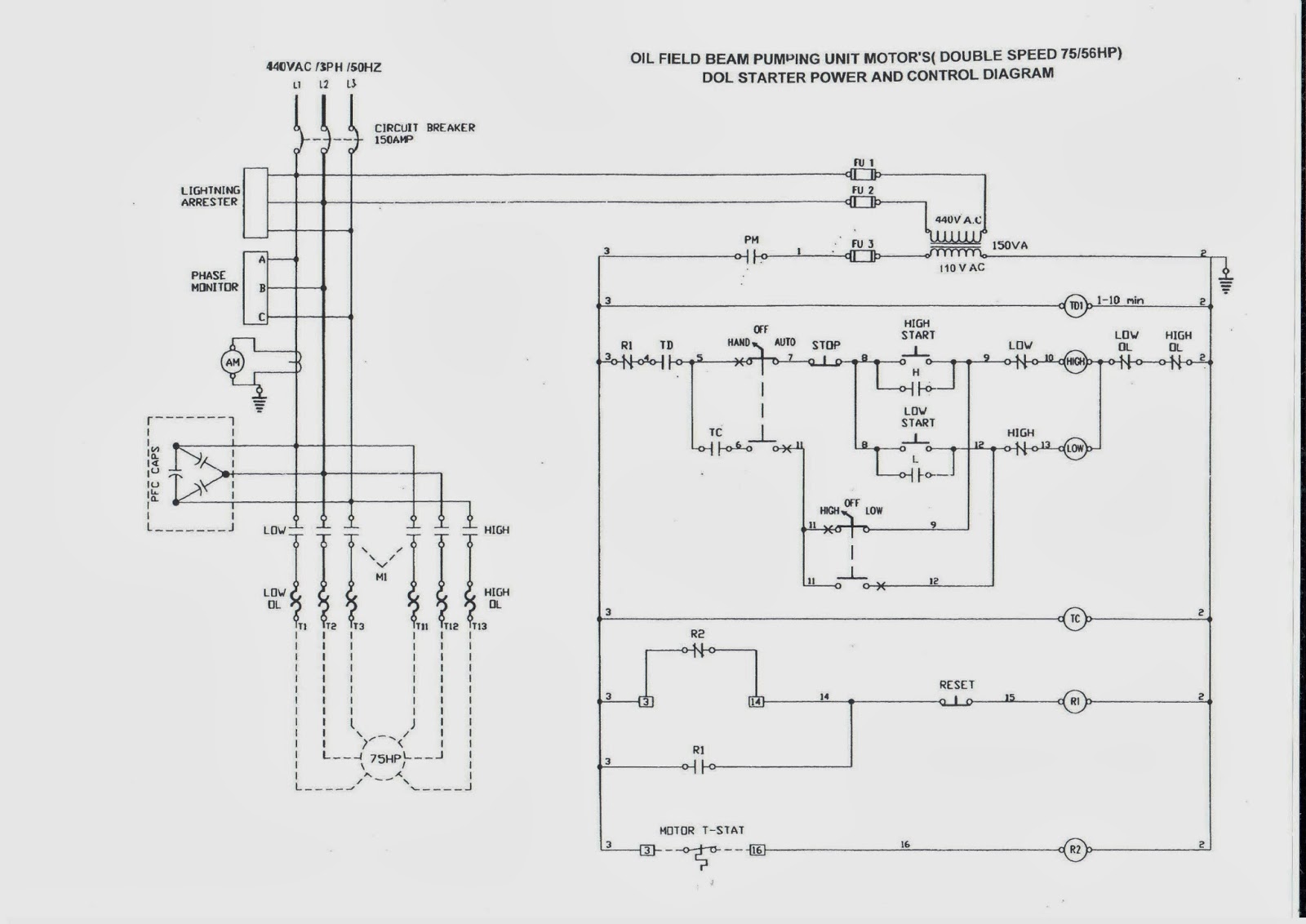
OIL AND GAS ELECTRICAL AND INSTRUMENTATION ENGINEERING: OIL FIELD BEAM

Central Air Conditioning Unit Installation